
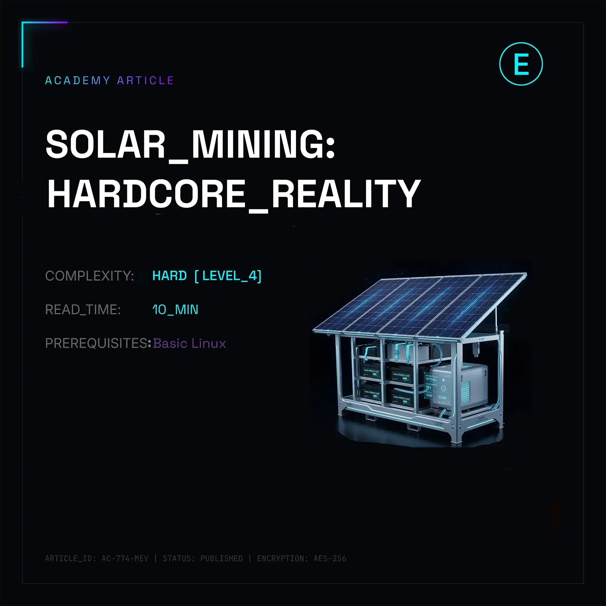
The idea of ditching grid tariffs and powering your crypto mining rig straight from the sun looks amazing on paper in some sales pitch deck. In reality, when you actually try to hook up an ASIC’s switching power supply—which expects a rock-solid, industrial-grade pure sine wave—to a photovoltaic system, you quickly hit a wall of brutal engineering reality.
Six months ago at one of our sites, we managed to fry three high-end Chinese inverters in a single week before it finally clicked just how much miner electronics absolutely despise off-grid power generation.
Architectural Pitfalls: Off-Grid vs. Hybrid
If you think you can just set up some panels, a charge controller, a couple of batteries, and plug in something like an Antminer S21—I’ve got bad news for you. An ASIC isn't a household refrigerator. It’s a completely static, heavy load that demands, say, 3.5 kW right here, right now, 24/7. Solar doesn't work that way. Its production curve is a bell curve that constantly gets chopped to pieces by passing clouds. When that happens, your PV output can plummet by 80% in a matter of seconds.
Going completely Off-grid without a utility backup is pure masochism. To keep the system alive, you'd have to build a massive LiFePO4 battery bank. Even then, the real round-trip efficiency across the "panels -> controller -> battery -> inverter -> ASIC PSU" chain drops down to around 75–83%. A massive amount of energy is just wasted as heat during conversion.
A hybrid setup (Grid-tied with a buffer) is much more sensible. The grid acts as an infinite buffer. When the sun is out, you draw from solar; a cloud rolls in, and the inverter instantly (or not quite) pulls the missing delta from the wall. Efficiency here is solid, close to 95%, because of the direct DC-to-AC conversion. But if you are completely off the grid, it’s just you vs. power electronics.
What Happens Inside the PSU When the Inverter Chokes
Stock miner power supplies (like the APW12 or APW17) are engineered for clean sine waves with minimal total harmonic distortion (THD < 3%). Most budget inverters, even if they claim to output a Pure Sine Wave, spit out a heavily distorted, choppy trapezoidal wave under real-world loads.
- The first roadblock you'll hit is the active power factor correction (APFC) inside the ASIC's power supply. The APFC algorithm tries to match current consumption to the voltage waveform. Meanwhile, the inverter tries to stabilize the voltage based on the load. When they clash, their PWM controllers start fighting each other. The system ends up in a self-oscillating resonance: the inverter starts whining loudly, the ASIC squeals, and within a few minutes, the inverter's power MOSFETs blow up from overheating.
- The second issue is dynamic load step. When the ASIC's control board commands the hashboards to spin up, power consumption jumps from a couple hundred watts to three or four kilowatts almost instantly. The inverter can't handle the sudden spike, causing the output voltage to drop below 180V. This triggers the under-voltage protection (UVP) on the PSU, and the ASIC reboots. During testing, we hit a boot loop every 10 minutes, which completely trashes the control board's flash memory in a couple of days.
Because of this, your battery buffer capacity must be strictly calculated: E_bat >= P_asic * 0.5 hours. That’s the bare minimum required to smooth out the sag while the inverter digests the changes in solar output. Furthermore, the inverter's rated capacity should be at least 35–50% higher than the farm's peak draw. If you have a 10 kW rig, you need a 15 kW inverter, or its protection circuits will trip over every little hiccup.
Automating the Sh*tshow via RPC and Modbus
The only way to avoid frying your gear without babysitting it 24/7 is to dynamically throttle the ASIC's hashrate based on how much solar power your panels are actually bringing in.
Below is a production-ready Python script. It polls the inverter over Modbus TCP (register addresses are mapped for popular Chinese hybrid inverters like Deye/Sunways), pulls the current PV output, and uses JSON-RPC to swap power profiles on ASICs running custom firmware (like Braiins OS or VNISH).
import time
import logging
import requests
from pymodbus.client import ModbusTcpClient
# Logging setup (clean and simple)
logging.basicConfig(level=logging.INFO, format='%(asctime)s [%(levelname)s] %(message)s')
# Config
INVERTER_IP = "192.168.1.50"
INVERTER_PORT = 502
REG_SOLAR_POWER = 40082  # PV power register for Deye/Sunways
ASIC_IP = "192.168.1.100"
ASIC_URL = f"http://{ASIC_IP}:4028/api"  # Standard endpoint for custom firmware
SHUTDOWN_THRESHOLD = 1000  # Below 1kW — shut down mining
# Profiles (sorted descending to make iteration easier)
POWER_PROFILES = [
    {"min_watt": 3200, "profile": "Performance_3500W"},
    {"min_watt": 2200, "profile": "Balanced_2400W"},
    {"min_watt": 1100, "profile": "Eco_1200W"}
]
def get_solar_power():
    """Poll the inverter cleanly via pymodbus"""
    client = ModbusTcpClient(INVERTER_IP, port=INVERTER_PORT)
    try:
        if client.connect():
            # Read 1 register (holding register = 3)
            res = client.read_holding_registers(REG_SOLAR_POWER, 1, slave=1)
            if not res.isError():
                return res.registers[0]
            logging.error(f"Modbus error: {res}")
    except Exception as e:
        logging.error(f"Inverter disconnected: {e}")
    finally:
        client.close()
    return 0
def send_asic_cmd(cmd, param=None):
    """Send an RPC request to the ASIC"""
    payload = {"command": cmd}
    if param:
        payload["parameter"] = param

    try:
        # Custom firmwares (Vnish/Braiins) usually accept standard POST with JSON
        r = requests.post(ASIC_URL, json=payload, timeout=3)
        if r.status_code == 200:
            return r.json()
    except Exception as e:
        logging.error(f"ASIC request {cmd} failed: {e}")
    return {}
def main():
    logging.info("Solar-Mining balancing script started.")
    last_profile = None

    while True:
        solar_pwr = get_solar_power()
        logging.info(f"Solar output: {solar_pwr}W")

        if solar_pwr < SHUTDOWN_THRESHOLD:
            if last_profile != "paused":
                logging.warning("Low solar power. Pausing hashboards.")
                send_asic_cmd("pause")
                last_profile = "paused"
        else:
            # Find the best profile for current power output
            selected_profile = None
            for p in POWER_PROFILES:
                if solar_pwr >= p["min_watt"]:
                    selected_profile = p["profile"]
                    break

            if selected_profile and selected_profile != last_profile:
                logging.info(f"Switching to profile: {selected_profile}")
                send_asic_cmd("resume")
                res = send_asic_cmd("setprofile", param=selected_profile)

                # Check status (for VNISH / Braiins)
                if res.get("STATUS", [{}])[0].get("STATUS") == "S":
                    last_profile = selected_profile
                    logging.info("Profile changed successfully.")
                else:
                    logging.error(f"ASIC rejected profile: {res}")

        # 30-second delay so we don't spam the ASIC's control board
        time.sleep(30)
if __name__ == "__main__":
    main()
Field Notes: How to Build Your Rig and Not Go Broke
Instead of giving you pretty lists out of a textbook, here is the raw, no-nonsense takeaway from our hands-on experience, paid for with a ton of wasted time and fried silicon.
- First, forget about high-frequency (transformerless) inverters if you are building a pure off-grid system. You need heavy-duty, low-frequency iron with massive toroidal transformers on the output (like a Victron MultiPlus or industrial-grade equivalents). Thanks to their high inductance, they tolerate the messy power factor and brutal current spikes thrown at them by ASIC power supplies.
- Second, run separate grounding loops. Hashboards generate an insane amount of high-frequency electrical noise on the chassis. If you tie your solar panel frames, trackers, and miner racks to the same physical ground loop, that interference will drive your charge controllers (MPPT) crazy. One fine day, they'll lock up completely open and dump the maximum raw panel voltage straight into your inverter.
- Third, always install SPDs (Surge Protective Devices) rated for Type 1+2 / Class B+C on both the DC side from the panel strings and the AC side right after the inverter. When voltage drops, miner PSUs love to kick reverse inductive spikes back into the circuit. Without robust surge protection, your inverter will eventually start throwing consistent Overcurrent faults, even when there's barely any load.
The Cold Hard Math: Why Standard ROI Calculators Are Total Fiction
If you open up any solar panel savings calculator online, they’ll estimate a payback period of about 3 to 4 years. Marketers love to take the total nameplate capacity of the panels, multiply it by the average peak sun hours in the region, and claim you’re getting "free juice." In the crypto mining world, this math smacks face-first into the brutal reality of erratic solar generation.
Let’s break down a typical setup: a 15 kW solar array paired with three ASICs drawing a combined 10.5 kW. Here is how the actual power distribution looks throughout the day on a perfect summer day:
| Time Window | PV Generation (Avg) | Rig Consumption | Power Flow & Behavior |
|---|---|---|---|
| 00:00 – 06:00 | 0 kW | 0 kW (or 10.5 kW from grid) | The rig is either sitting idle or sucking expensive off-peak grid power. You can't drain your batteries here—you'll kill them in 300 cycles. |
| 06:00 – 09:00 | 3 – 6 kW | 3.5 kW (1 ASIC) | The automation script spins up the first miner. The remaining solar juice goes toward trickle-charging the battery bank after its overnight idle discharge. |
| 09:00 – 15:00 | 12 – 14 kW | 10.5 kW (3 ASICs) | Peak performance window. All three machines are hashing at full tilt. The 1.5–3.5 kW surplus tops off the buffer batteries. |
| 15:00 – 18:00 | 5 – 8 kW | 7.0 kW (2 ASICs) | The sun starts setting. The script kills one ASIC to keep the inverter from aggressively draining the battery bank. |
| 18:00 – 24:00 | 0 – 2 kW | 0 kW (or 10.5 kW from grid) | Full off-grid system shutdown. |
The Bottom Line: Out of 24 hours in a day, your ASICs are hashing at 100% capacity for only about 6 hours. For another 6 hours, they are running at 30–60% capacity. The rest of the time, your expensive hardware is just sitting there catching dust and losing its edge while network difficulty climbs day by day.
If you run a pure Off-grid operation, your equipment utilization rate (Capacity Factor) tanks to around 35–40%. This means the ROI timeline for the ASICs themselves gets multiplied by exactly 2.5. Your gear will become obsolete and turn into a pumpkin before it even breaks even.
The Hidden Gotchas (What Hardware Vendors Won't Tell You)
Thermal Drift in Panels and ASICs
Miners dump a staggering amount of heat into their surroundings. Solar panels are most efficient at a cell temperature of 25°C. For every 1°C above that threshold, silicon generation drops by roughly 0.4%.
If you position your ASIC hot-air exhaust anywhere near the solar array where it can get sucked under the panels, you will lose 15–20% of your power generation out of thin air. At a site we deployed out in Texas, we spent days scratching our heads trying to figure out why our noon generation was tanking below estimates, until we redirected the cooling fans away from the roof hosting the PV array.
Current Spikes in Hashboards During Voltage Sags
When the inverter is pushed to its limits and the voltage drops, the built-in DC-DC converter on the ASIC's hashboard tries to maintain the voltage assigned to the chips (say, 0.36V). To compensate for the input voltage drop, it starts pulling more input current.
If your inverter is spitting out high-frequency ripples, these sudden current spikes will fry the power phases (MOSFETs) right on the hashboard. You end up with a textbook nightmare scenario: your power supply is completely fine, the inverter is throwing an error code, but your hashboard's power rails are blown and the chips are dead shorted.
An Engineer's Final Verdict
Building a solar-powered autonomous mining setup only makes sense in two specific scenarios:
- You are using free or dirt-cheap used gear from a previous generation (like old Antminer T17/S19 units that you don't mind running into the ground for 8 hours a day). Buying flagship hydro rigs or top-tier S21 units to run on solar is financial suicide because of the massive idle time at night.
- You are running a solid hybrid setup tied to the grid, where solar is used strictly to shave off peak daytime consumption, and the farm switches to cheap, subsidized grid tariffs at night.
All the other romantic ideas about "green mining in the middle of nowhere" usually end with a pile of fried MOSFETs, abused batteries, and an automation script working overtime just to keep this shaky house of cards from rebooting yet again.